MELSEC iQ-R Series Motion Module (RD78G) - Drive configuration and programming from the PLC side
MELSEC iQ-R Series Motion Module (RD78G) - Drives configuration and programming from the PLC side

It is the article from the series
Melsec iQ-R Series Motion Module (RD78G) Quick Start Guide.

In this part you will learn how to:
- connect the limit switches and forced stop function to the servo amplifier,
- set the basic servo parameters,
- import the PLC Open library to the PLC project,
- declare the AxisRef structure from the PLC side,
- power axes (switching them in servo on),
- reset Motion module errors,
- performing the JOG operation on the axes,
- declare the AxisRef structure from the PLC side,
- power axes (switching them in servo on),
- reset Motion module errors,
- performing the JOG operation on the axes,
1. LSP, LSN and EM2 device connection
The LSP (Forward Stroke Limit), LSN (Reverse Stroke Limit) and the EM2 (Forced Stop) devices are assigned to the CN3 connector.
The details of the CN3 connector assignment for all MR-J5 servo amplifiers are to be found in the "Connectors and pin assignment" in "SIGNALS AND WIRING" chapter of the Hardware MR-J5 User's Manual. In this article it will be shown how to connect these devices to MR-J5W3-G servo amplifier.
The illustration above shows the placement of the CN3 connector's pin.
The initially assigned device of the CN3 connector are as shown on the illustration below:
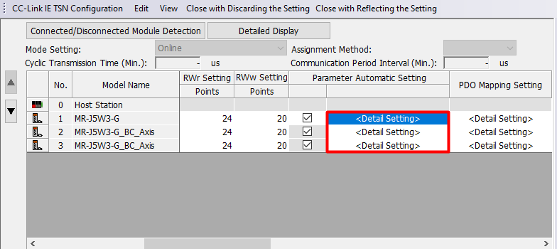
The initial assignment of the connector pins within one servo axis can be changed. To do that connect the servo amplifier to PC, open or create the new project or open the existing one and choose Parameter → Module Information → RD78Gn → Module Parameter (Network) → Basic Settingh → Network Configuration Settings then double-click <Detailed Setting>.
In the newly opened window double-click
Detail Setting of the
Parameter Automatic Setting of servo amplifier
.
The Parameter Setting window will show up. From the left list choose Function display (List) → I/O.
In the Digital I/O window click the Setting button of the axis to be set.
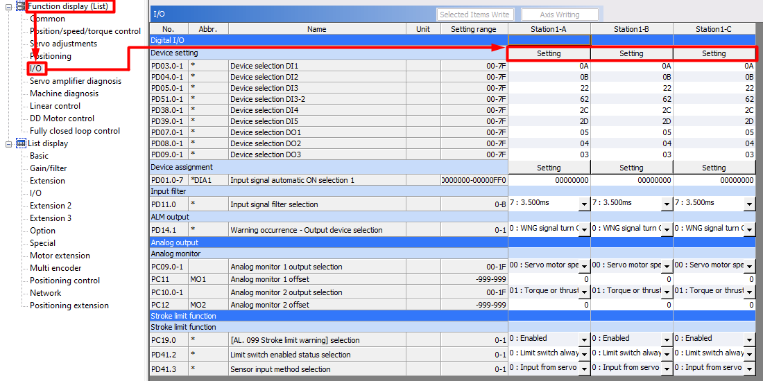
The following window will appear:
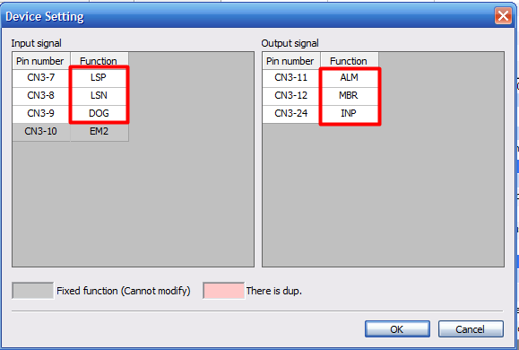
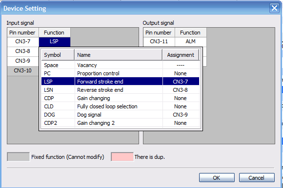
To change the Device Assignment left-click on the Device in Function column.
The Parameter Setting window will show up. From the left list choose Function display (List) → I/O.
In the Digital I/O window click the Setting button of the axis to be set.
The following window will appear:
To change the Device Assignment left-click on the Device in Function column.
2. Axis parametrization - Motion module side
This section requires an established and pre-configured project. For a description of how to do this, see the first article from the
Melsec iQ-R Series Motion Module (RD78G) Quick Start Guide series
- System start-up.
In the project tree left-click the
Parameter → Module Information → 00n:RD78Gn → Module Extended Parameter. Window with the Motion module settings will appear.
In newly opended window right-click on added Axes from the Axis tab. You will enter the Axis Parameter Setting.
In newly opended window right-click on added Axes from the Axis tab. You will enter the Axis Parameter Setting.
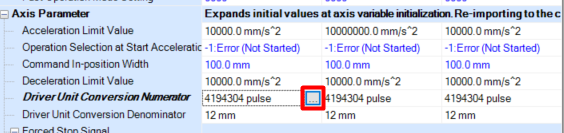
Setting the units in which the axis operates and the parameters of the electronic gear
To set the units and electronic gear find
Driver Unit Conversion Numerator
and righ-click
[...] as shown on the picture below.
After that you will enter the
Electronic Gear Settings of given axis.
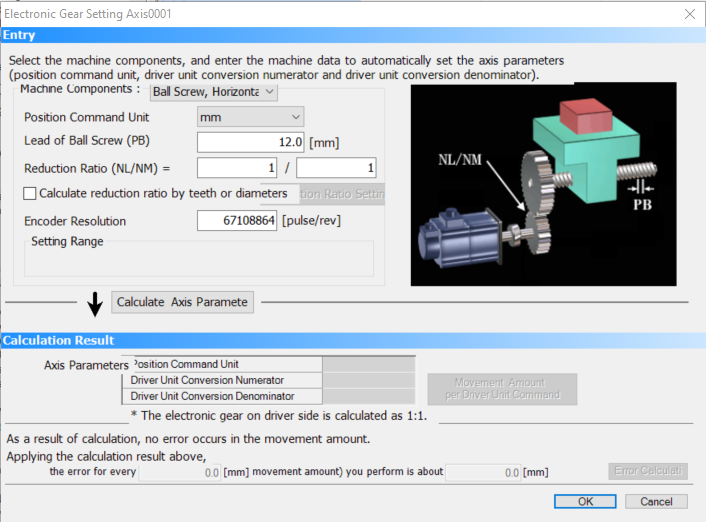
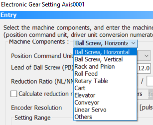
In this window you should first choose machine components.
There are several options depending on the gears used and the orientation of the drive. In this article,
Machine Components is set as Ball Screw.
To set the units used expand the
Position Command Unit list and choose which units you want to use. There are several options depending on the Machine Components selected.
Also depending of the Machine Components selected you will have to set the additional information about the components used such as lead of the ball screw.
If you use gearbox set the values given in
Reduction Ratio. If you do not know the value of reduction ratio you can calculate it automatically by number of gears teeth or diameters. To do so set the
Calculate reduction ratio by teeth or diameters checkbox and enter the
Reduction Seeting Window.
Once the values have been set confirm it by pressing
OK button.
If you are not using a gearbox set the
Reduction Ratio as 1/1
The last parameter which has to be set is
Encoder Resolution specified in pulses per revolution. Enocoders of the MR-J5 series servo motors have a resolution of 67 108 864 [pulse/rev] and this value has to be written as
Encoder Resolution.
After specyfing all of the parameters value press
Calculate Axis Parameters button. It will calculate electronic gear parameters. Calculated parameters are shown on the bottom part of the window.
Press OK to confirm the changes.
3. Importing the PLCopen library into a GX Works3 project
You can download the PLCopen library for RD78G from:
https://pl3a.mitsubishielectric.com/fa/pl/dl/13647/
To import the PLCopen library you have to select
Project on the top bar of GX Works3 and select
Library Operation → Register to Library List → Library as shown on the picture below:
Accept the prompt window by pressing
OK button. You will be taken to the file selection window. Find and select library file (.mlsm extension).
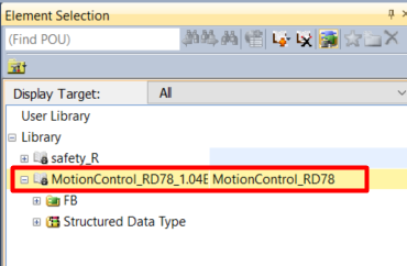
Correctly added library will be displayed on the Library tab of the Element Selection window:
4. Declaration of AxisRef structure
This chapter shows how to register the axis information (AxisRef) of the real drive axis as a public label to use it in the project on PLC.
1) Enter
00n:RD78Gn → Module Extended Parameter from the GX Works3 project tree.
2) Double-click
Label → Global Label → Ax+Global in the navigation window of the motion control setting function and set the
Public Label column of the target labels to
Enable.
3)
Double-click Structured Data Types
→ AXIS_REAL
and set the
Public Label
column of the AxisRef to
Enable
.
The other public labels are registered in the same way.
After registration you need to reflect registered public labels. After the labels are reflected the PLC CPU can use the members registered as public labels.
1) In the motion control setting function select
Convert → Rebuild All to convert all public labels.
2) Select
Convert → Reflect Public Labels and click the
Yes button on the confirmation screen.
3) Convert all the program in GX Works3 for the PLC CPU to use the public labels. The reflected public labels are registered in the element selection window.
5. Activation of individual axes via MC_Power function block
Settings for global and public labels
Before executing a function block, it is useful to create variables on which we will operate. The most effective way to do this is to use structures. We create the stAxis structure, in which we nest a structure containing the variables to operate on the MC_Power function block as shown below:
Next, we create a global structural variable to store the data for axis one:
We can use the variables created in this way for axis powering operations.
Creating a worksheet in a Scan-type program.
To add new worksheet we need to right-click on program block
ProgPou and select
Add New Worksheet.
After adding new worksheet you can change it name to more suitable like
ServoControl.
PLC READY [Y0] turning on
Regardless of the programming language, PLC READY [Yn*0] needs to be turned ON by a PLC CPU to start operation of the Motion module.
The best way to do it is to turn PLC READY flag when the PLC CPU is powered ON and the synchronization flag [Xn*1] is turned ON:
*n stands for the I/O number of the Motion module
Adding MC_Power function block
To add MC_Power function block go to
Library tab of the
Element Selection window and unfold
MotionControl_RD78_1.04E → FB → Management. Find
MC_Power FB, drag and drop it over your program workspace.
After dropping FB you have to assign the corresponding variables to inputs and outputs of the FB.
Description of the inputs of the MC_Power function block
On the input side:
-
Enable - While is TRUE, the axis control is valid (BOOL).
-
ServoON - Specifies the servo ON request (BOOL).
-
Axis - Axis information available from AxisRef structure (AxisRef).
On the output side:
-
Status - Indicates that the servo amplifier is ready for operation (BOOL).
-
ReadyStatus - Indicates the ready ON/OFF status (BOOL).
- Busy - Indicates that the FB is in execution (
BOOL
).
-
Error - When TRUE, it indicaes that and error has occured in the FB (BOOL).
-
ErrorID - The error code generated in the FB is returned (WORD).

For the details description of MC_Power FB refer to MELSEC iQ-R Motion Module User's Manual (Motion Control Function Blocks).
Example of a FB with defined I/O
In this example, the first axis will be turned on
servo on when the Motion module is switched on, provided the low state on the variable i_bServoOn.
Using the MC_Reset function block to reset a Motion module errors
When an error occurs in the Motion module, we must reset it in order to continue operation on the servo axes. To do this, the library offers us the MC_Reset FB.
Let's create a new structure with variables to control FB. We will call it stErrorsReset.
After creating the stErrorsReset structure, we nest it in the stAxis structure.
Description of the inputs of the MC_Power function block
On the input side:
-
Execute - When TRUE the FB activates (BOOL).
-
Options - No need to specify (BOOL).
-
Axis - Axis information available from AxisRef structure (AxisRef).
On the output side:
-
Done- Indicates that reset has been completed (BOOL).
- Busy - Indicates that the FB is in execution (BOOL).
-
CommandAborted - Indicates that the command has been aborted because of timeout. Becomes FALSE because of
Execute = FALSE (BOOL).
-
Error - When TRUE, it indicaes that and error has occured in the FB (BOOL).
-
ErrorID - The error code generated in the FB is returned (UNSIGNED WORD).
For the details description of MC_Reset FB refer to MELSEC iQ-R Motion Module User's Manual (Motion Control Function Blocks).
Example of a FB with defined I/O
In this example, Motion module's errors will be reset when the variable i_bExecute is turned on.
Using MCv_Jog FB for manual mode operations on the servo axis
MCv_Jog allows you to manually control the position of an axis with set motion parameters. As usual we will create structure to control this FB. Let's name this structure
stJOG.
After creating stJOG, nest it in the stAxis structure.
Description of the inputs of the MCv_Jog function block
On the input side:
-
JogForward - Positive rotation JOG command. When TRUE, it executes FB (BOOL).
-
JogBackward - Negative rotation JOG command. When TRUE, it executes FB (BOOL).
-
Acceleration - Sets the acceleration (LREAL).
-
Deceleration - Sets the deceleration (LREAL).
-
Jerk- Sets the jerk (LREAL).
-
Options - No need to specify (BOOL).
-
Axis - Axis information available from AxisRef structure (AxisRef).
On the output side:
-
Done - Execution completion. When deceleration stop by JOG command OFF is completed,
Done bit becomes TRUE for only one scan (BOOL).
- Busy - Indicates that the FB is in execution (BOOL).
-
Active - Indicates that the FB is controlling the axis (BOOL).
-
CommandAborted - Indicates that the execution has been aborted (BOOL).
-
Error - When TRUE, it indicaes that and error has occured in the FB (BOOL).
-
ErrorID - The error code generated in the FB is returned (UNSIGNED WORD).
For the details description of MCv_Jog FB refer to MELSEC iQ-R Motion Module User's Manual (Motion Control Function Blocks).
Explanation of Jerk function
Jerk is the temporal change ratio of the acceleration or deceleration. The unit is U/s
3
where U stands for selected command unit
. When the jerk is set, since the velocity waveform shows a S-shape and the axis can smoothly accelerate and decelerate at the start and the end of acceleration and deceleration, it can reduce the burden on the motor and impact on the machine.
The sum of the time required to reach the target acceleration after startup and the time from the target acceleration to the acceleration 0 at the end of acceleration is called the jerk applying time. The ratio of jerk applying time to acceleration (deceleration) time is called the jerk applying ratio.
The jerk applying time and the jerk applying ratio can be calculated with the following formulas:
Jerk applying time = 2
×
Target acceleration ÷ Jerk
Jerk applying ratio = (Jerk applying time ÷ Acceleration time)
×
100 [%]
For the details description of Jerk function refer to MELSEC iQ-R Motion Module User's Manual (Motion Control Function Blocks).
Example of a FB with defined I/O
To trigger axis movement, define velocity, acceleration, deceleration greater than 0 in the
i_leVelocity,
i_leAcceleration,
i_leDecleration variables and then activate FB by selecting positive or negative axis rotation direction through the
i_bJogForward or
i_bJogBackward variables. You can also define the acceleration time on the Jerk input via the
i_leJerk variable but it is not necessary.
Related Articles
MELSEC iQ-R Series Motion Module (RD78G) - Reading and writing servo parameters from PLC side
MELSEC iQ-R Series Motion Module (RD78G) - Reading and writing servo parameters from PLC side It is the article from the series Melsec iQ-R Series Motion Module (RD78G) Quick Start Guide. In this part you will learn how to: - execute reading of ...MELSEC iQ-R Series Motion Module (RD78G) - System start-up
MELSEC iQ-R Series Motion Module (RD78G) - System start-up It is the first article from the series Melsec iQ-R Series Motion Module (RD78G) Quick Start Guide. In this part you will learn how to: - create the PLC project, - add the Motion Module to ...MELSEC iQ-R Series Motion Module (RD78G) - Homing from the PLC side
MELSEC iQ-R Series Motion Module (RD78G) - Homing from the PLC side It is the article from the series Melsec iQ-R Series Motion Module (RD78G) Quick Start Guide. In this part you will learn how to: - connect sensor to the DOG signal - set sensor ...MELSEC iQ-R Series Motion Module (RD78G) - Speed and torque control mode from the PLC side
MELSEC iQ-R Series Motion Module (RD78G) - Speed and torque control mode from the PLC side It is the article from the series Melsec iQ-R Series Motion Module (RD78G) Quick Start Guide. In this part you will learn how to: - controlling the speed of ...MELSEC iQ-R Series Motion Module (RD78G) - Interpolation of multiple axes from PLC side
MELSEC iQ-R Series Motion Module (RD78G) - Interpolation of multiple axes from PLC side It is the article from the series Melsec iQ-R Series Motion Module (RD78G) Quick Start Guide. In this part you will learn how to: - declare axes groups and ...